
A 27-Hour Print to Solve a Radar Packaging Problem
A 27-Hour Print to Solve a Radar Packaging Problem
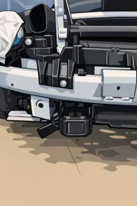
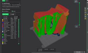
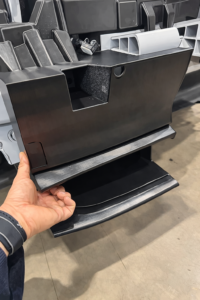
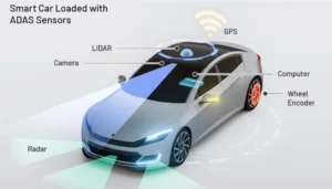
Prototype context, print strategy, and system-level constraint. One problem, three views.
A 350 × 345 × 300 mm local fascia 3D print.
One ADAS radar.
And a reminder that CAD clearances still need real-world testing.
The moment
It starts the same way every time.
A new front-end package comes in.
A radar needs a home.
Styling wants it invisible.
Manufacturing wants good draft angle.
The sensor wants perfect alignment.
And then the “simple” part becomes a system problem.
In this case, the CAD was not wrong.
Target clearances were met. Nominal angles were respected.
And yet, once the confirmation prototype was built and tested, radar performance dropped by roughly 10%.
That result matters. Because it safety performance is a must.
When CAD is right and reality is still wrong
This is the uncomfortable zone between nominal geometry and physical behavior.
Several contributors were still open questions:
Confirmation prototype fascias do not behave like production parts. Stiffness and sag can be directionally correct but not magnitude-correct.
A slightly longer styling surface can extend deeper into the radar near-field without violating any clearance targets.
Nearby metallic structures may still meet spacing rules while altering the electromagnetic environment.
None of these show up as red flags in CAD.
All of them show up in performance data.
At this stage of a program, that distinction matters. Because there is still a narrow window to react before production tooling is locked.
Why radar packaging is different
A modern automotive long-range radar is not just “a sensor behind the bumper”.
Most production systems operate in the 76–77 GHz band using FMCW (frequency-modulated continuous wave) technology. A single unit often combines wide short-range coverage with narrow long-range coverage. Published examples describe short-range fields of view approaching ±90° and far-range fields of view closer to ±9°, with detection distances up to ~250 m, depending on the sensor.
Small angular errors at the mounting interface become measurable errors on the road.
And unlike a camera, those errors may not be obvious until you are deep into system testing.
The hidden enemy: what’s in front of the radar
The most common trap is assuming the bumper cover is “transparent enough”.
At radar frequencies, materials and coatings matter. Metallic pigments in automotive basecoats can significantly increase effective permittivity, increasing reflection and attenuation through the paint stack. Public technical studies on automotive radar transparency show that coating composition and thickness can measurably reduce radar performance.
In practical terms:
A radar can be “behind the bumper” and still be partially blind.
Small coating or geometry changes can produce measurable performance shifts.
Repair or repaint events can become functional issues, not just cosmetic ones.
This is invisible physics operating inside visible geometry.
Why we 3D print at this stage
For this kind of integration work, printing is not about appearance. It is about truth.
We print to:
Confirm real packaging clearances
Validate mounting faces and bracket stiffness
Check service access and installation reality
Expose interactions CAD cannot predict
But large prints introduce their own constraints:
Long prints move with temperature
Warpage becomes a geometry error
Supports become a design input, not an afterthought
When your print time is measured in days, bad assumptions get expensive.
This particular prototype was sized to a 350 × 345 × 300 mm build volume, with a slicer estimate of approximately 27 hours and ~1.52 kg of filament.
At that point, you are not printing a part.
You are committing to a process.
Changing the prototype to reduce unknowns
The response was not to immediately “fix the model”.
It was to change how reality was represented.
The next iteration focused on removing ambiguity:
A single-piece PC-ABS print to reduce stack-up
Direct locating features to the front beam, shared with the radar bracket
Elimination of intermediate interfaces that could introduce tilt or compliance
- Local stiffness ribs behind the radar area to reduce warpage and gravity-driven deformation during and after the print
The intent was not to make it prettier.
It was to separate geometry error from physics effects.
Only once those are isolated does the data become actionable.
Sag, stiffness, and RF do not live in separate worlds
Large fascia parts do not only move under load.
They move under their own weight.
When a confirmation prototype fascia sags, the radar does not see “sag”.
It sees:
A shifted radome thickness
A changed incidence angle
A modified near-field boundary condition
A 10% performance drop does not require a dramatic change.
It only requires a consistent one.
What we check before we trust a radar mount
Before calling a radar mount “good”, we run a short but disciplined checklist:
Mounting plane control
Flatness and repeatability matter more than visual straightness.
If it can shift during torque-up, it will.
Angle discipline
Pitch and yaw errors become range and lateral errors quickly.
Design for locating features, not just fasteners.
Radome and coating awareness
Treat bumper, primer, basecoat, and clearcoat as an RF stack, not a cosmetic stack.
Field-of-view protection
Ducts, ribs, brackets, and harnesses creep over time.
Short-range and long-range coverage must both remain clean.
Build and service reality
If the plant can install it “almost right”, that is how it will be installed.
Design the system so “almost right” is impossible.
The real insight
Radar integration is where mechanical engineering meets invisible physics.
The risk is not bad design.
The risk is trusting nominal geometry when behavior lives in tolerances, materials, and gravity.
This is why we print early, mount honestly, and test before tooling.
That is the purpose of these Engineering Insights:
Real problems. Real constraints. Real decisions made while there is still time to change the outcome.
1 Comment. Leave new
[…] Read next: A 27-Hour Print to Solve a Radar Packaging Problem […]