
Anatomy of a New Car Program: What It Actually Takes to Go from Concept to Start of Production
Anatomy of a New Car Program: What It Actually Takes to Go from Concept to Start of Production
OCMEE Design Engineering Insights – Vehicle Program Series
A new car does not begin with a sketch. It begins with a spreadsheet. A business case. A volume target. A price point someone had to defend to a room full of executives who wanted the numbers to work before anyone picked up a pencil. The sketch comes later. And between that sketch and the first customer vehicle rolling off the line, there are three to five years of relentless, cross-functional engineering: thousands of decisions, hundreds of suppliers, millions of hours of simulation, and a stage-gate process that exists for one reason: to prevent the program from collapsing under its own complexity. Most people outside the industry see a car launch and think it happened fast. It didn’t. This article walks through what a new vehicle program actually looks like from the inside: the phases, the teams, the decision points, and the engineering realities that separate programs that ship from programs that stall. This analysis reflects the program-level engineering perspective OCMEE Design brings to OEM and supplier engagements, from body structure and closures through manufacturing readiness. The following describes industry-standard vehicle development processes, illustrated with publicly known practices. 
Phase 0: Strategy and Product Definition
Before engineering begins, product planning defines what the vehicle needs to be. Segment. Target customer. Competitive set. Price bracket. Production volume. Finance builds the business case around these inputs: tooling investment, piece cost targets, return-on-investment timeline. This is not a creative exercise. This is capital allocation under uncertainty. The most consequential decision happens here: platform architecture.
Will the vehicle ride on an existing platform, or is this clean-sheet? That single decision reshapes the entire program. A platform-shared vehicle can shave 12–18 months off development and hundreds of millions off investment. A new architecture means new crash structures, new hard points, new supplier tooling, and significantly more capital at risk. The output is a product brief: a document every team in the program will reference for the next several years. It defines what the car is.
Everything that follows is how to build it.
Phase 1: Design. Where Vision Meets Packaging
The design studio takes the product brief and translates it into form. This is not just aesthetics. It is a negotiation. Exterior designers need to accommodate crash structure depths, cooling airflow, lighting regulations, aerodynamic targets, and pedestrian impact zones. Interior designers are constrained by occupant packaging, sightlines, airbag deployment zones, steering column adjustment ranges, and the electrical architecture that feeds every screen and switch. Most programs run a design competition. Two or three themes developed in parallel: sketches, digital models, full-size clay models. Leadership selects a direction. That theme moves into development, where design and engineering resolve every surface, shut line, and parting line together. The critical milestone: surface freeze.

The moment exterior and interior A-surfaces are mathematically locked. After surface freeze, engineering builds to those surfaces. Changes after this point are expensive, disruptive, and often visible in the final product as compromises nobody intended.
Surface freeze discipline separates mature programs from chaotic ones.
Phase 2: Engineering Development. The Long Middle
This is where the bulk of the work lives. And where most of the risk lives.
Engineering development typically runs 18 to 30 months, involving dozens of parallel workstreams that are deeply interdependent. A change in one system cascades through others. This is why automotive engineering is fundamentally a systems integration challenge, not a collection of component designs.
Body Structure (BIW), The vehicle’s skeleton. Structural members that carry crash loads, provide torsional stiffness for ride quality, and serve as the foundation for every other system. Material selection, steel, aluminum, carbon fiber, or mixed, drives joining strategies, weight, cost, and manufacturing complexity. For mixed-material construction, joint design becomes its own engineering discipline: self-piercing rivets, flow-drill screws, structural adhesives, each with different fatigue characteristics and process requirements. Body Exterior, Translating the studio’s frozen surfaces into production-feasible panels. Panel splits, attachment methods, tolerance strategies, sealing systems. For advanced materials like carbon fiber, this workstream also manages layup orientation, cure cycles, surface finish requirements, and the interface between composite panels and metallic structure. Class-A surface quality on composite panels remains one of the hardest problems in low-volume vehicle production. 

Closures: Doors, hood, decklid, and any movable body panels. Deceptively complex. Every closure must meet structural requirements (side impact, roof crush), seal against water and wind noise, operate reliably over tens of thousands of cycles, and maintain gap-and-flush tolerances that define perceived quality. Exotic mechanisms, scissor doors, butterfly doors, power-operated decklids, add an order of magnitude of kinematic, packaging, and electrical complexity. Hinge fatigue, gas strut degradation curves, latch engagement forces, check mechanisms, seal compression set over temperature cycles, closures engineering is a world of its own. 

Interior Systems, Everything the occupant touches and sees. Instrument panel, center console, door trim panels, headliner, seating, cargo management. Interior engineering is driven by safety (knee bolster energy absorption, airbag deployment clearances, head impact zones), ergonomics (reach studies, vision angles, ingress/egress), and increasingly, the integration of large digital displays and capacitive controls replacing physical buttons. The shift toward “hidden until summoned” interface philosophies adds complexity: motorized panels, ambient lighting integration, and surface materials that must be both aesthetically premium and functionally durable. 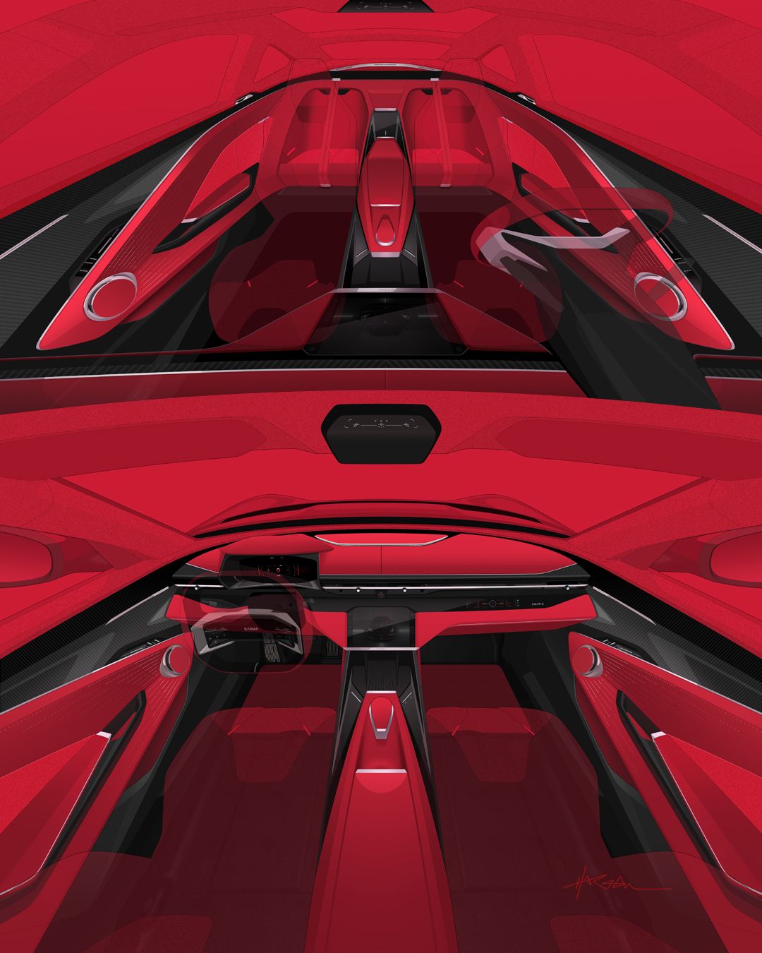
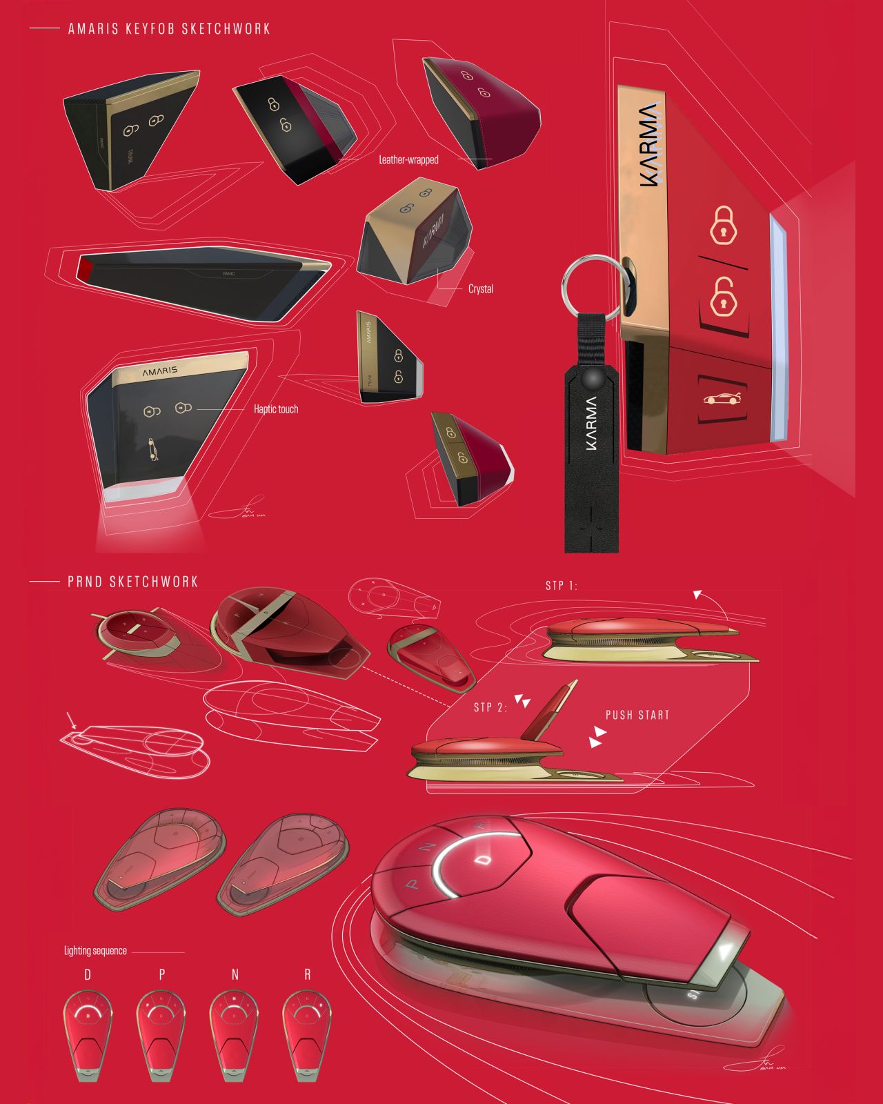
Chassis: Suspension geometry, steering feel, brake performance, ride quality. This team defines how the car drives. A sports car and a luxury sedan may share similar hardware, but the tuning is completely different. Spring rates, damper curves, anti-roll bar stiffness, steering rack ratio and assist maps. These are calibrated on real roads by experienced vehicle dynamics engineers making subjective judgments that no simulation fully replaces. Powertrain / Propulsion: For EVs: electric motor integration, battery pack design, thermal management, high-voltage architecture, charging systems. Battery packaging has cascading effects on body structure (floor height), interior packaging (headroom, console space), and vehicle dynamics (weight distribution, center of gravity height). Thermal management alone, cooling loops for motors, inverters, battery modules, and cabin HVAC, can involve 15+ heat exchangers with competing flow requirements. 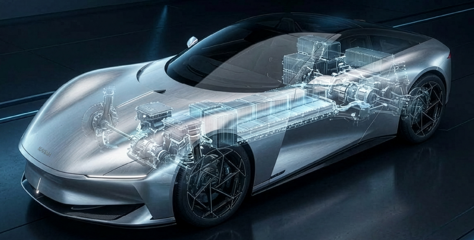
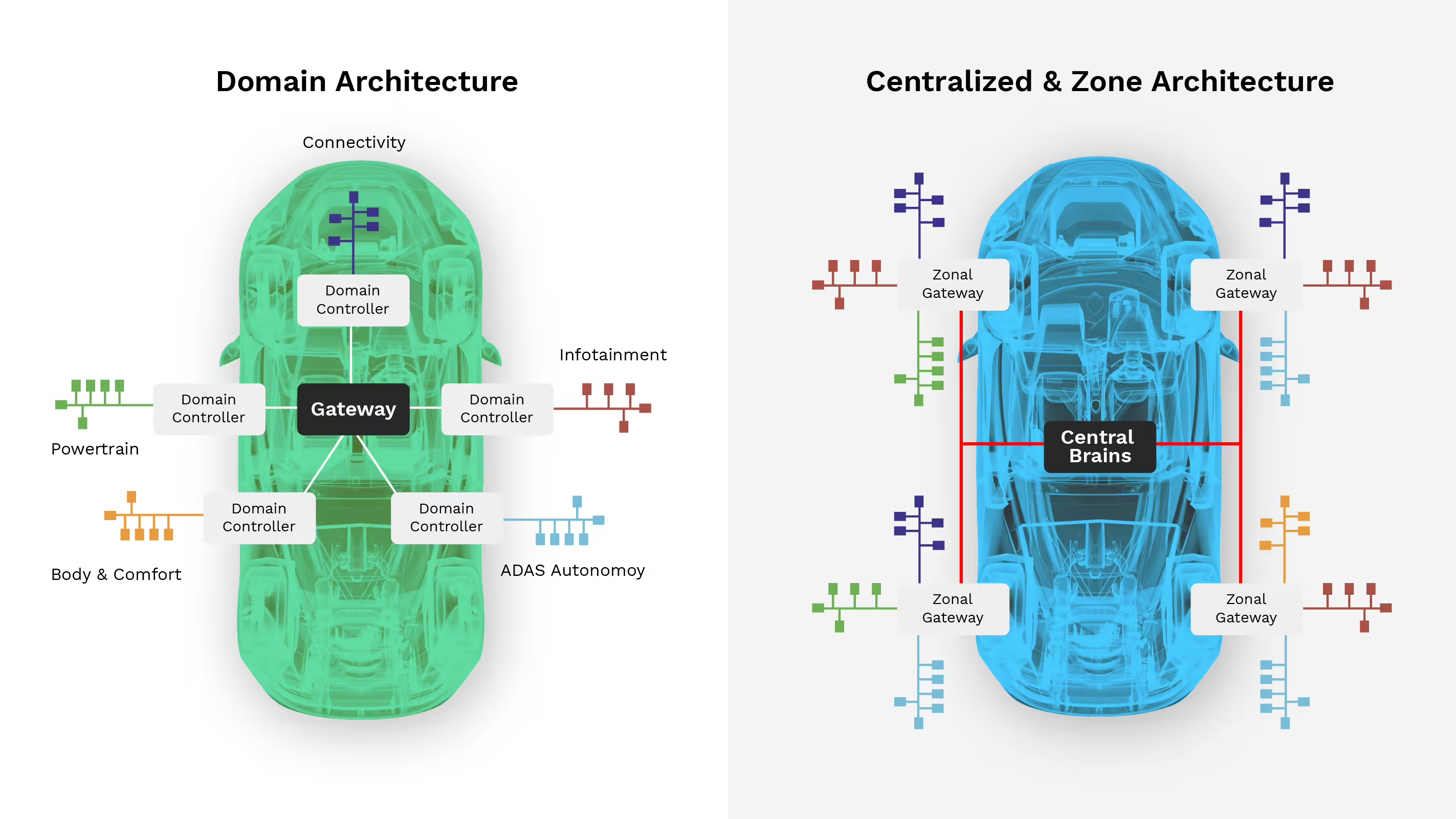
Electrical and Electronics (E/E), Increasingly the most complex and schedule-critical workstream. The wiring harness alone can contain several kilometers of wire and thousands of terminations. Modern vehicles are moving toward centralized compute architectures, zonal controllers replacing dozens of distributed ECUs, connected via automotive Ethernet backbones rather than legacy CAN/LIN buses. Software development for body controls, infotainment, ADAS, OTA infrastructure, and cybersecurity compliance (ISO 21434) often becomes the long pole in the program tent. Functional safety certification (ISO 26262) adds validation burden at every integration level.
None of these workstreams exist in isolation.
A change in battery pack height affects floor height, which affects interior headroom, which affects roof geometry, which affects the body structure, which affects crash performance. This cascading interdependence is why program management exists, to track thousands of connected decisions and prevent any single team from optimizing locally at the expense of the system. Phase 3: Simulation and Physical Validation
Throughout engineering development, the CAE team runs continuous analysis. Crash simulation: frontal, side, rear, pole, pedestrian impact. NVH: structural modes, acoustic transfer paths, panel radiation. Durability: fatigue life under road loads, suspension events, door slam cycles. CFD: external aerodynamics, underhood thermal management, brake cooling. Structural analysis: torsional stiffness, local strength, joint integrity. Simulation catches the majority of issues before metal is cut. But it does not catch everything. Physical prototypes are built in stages, mules first (test components installed in donor vehicles), then dedicated prototype builds representing the actual vehicle architecture. Validation testing is extensive and unforgiving:
Hot-weather testing. Arizona. Death Valley. Middle East. 50°C+ ambient. Cold-weather testing. Northern Sweden. Minnesota. –30°C soak starts. Altitude testing. Colorado. Sustained climbs at elevation. Corrosion testing. Salt spray chambers. Humidity cycling. Gravel bombardment. Water ingress. Full-vehicle shower testing at every angle and pressure. EMC testing. Electromagnetic compatibility in shielded chambers. Thousands of component-level tests. Every part has a DVP&R, Design Verification Plan and Report, defining tests, acceptance criteria, and program timing. Crash testing to regulatory standards, FMVSS in the U.S., Euro NCAP in Europe, is a hard gate. Failing a crash test late in the program can require body structure changes that cascade through tooling, timing, cost, and supplier commitments. There is no shortcut through validation. The physics does not negotiate. Phase 4: Manufacturing Engineering. Designing the Build
While the product engineers finalize the design, the manufacturing engineering team designs the production process. Stamping and forming: die design for body panels, press selection, blank optimization. Body shop: welding fixtures, robots, joining processes (for mixed-material vehicles: adhesive bonding, rivet-bonding, laser welding, each with different process windows). Paint shop: surface preparation, E-coat, primer, basecoat, clearcoat. Paint defects are the single largest source of rework in most assembly plants. General assembly: trim, chassis, and final lines where the vehicle comes together, station by station. For each workstation, manufacturing engineering defines the process, the tooling, the cycle time, and the quality checks. Line balancing, ensuring every station takes roughly the same time, determines plant throughput. Dimensional management runs through everything. On a premium vehicle, gap-and-flush targets may be ±0.5mm. That means the entire chain, from stamping through body shop through paint through final assembly, must be controlled to that precision. Measurement systems, fixture accuracy, and process capability studies (Cp/Cpk) are not optional. 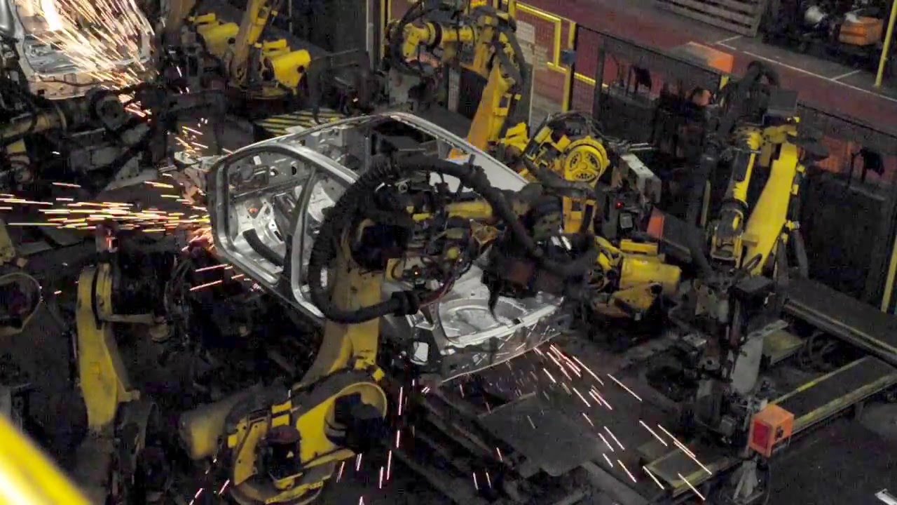
PFMEA (Process Failure Mode and Effects Analysis) identifies what can go wrong at each step. The control plan defines what gets measured, how often, and what triggers corrective action.
Phase 5: Supplier Development. You Don’t Build a Car Alone
A typical vehicle contains 3,000–5,000 unique part numbers sourced from hundreds of suppliers.
Procurement runs RFQs, negotiates contracts, and manages the APQP (Advanced Product Quality Planning) process with each supplier. PPAP (Production Part Approval Process) validates that every part from production tooling meets engineering specifications: dimensional, material, performance. Parts progress from prototype tooling to soft production tooling to hard production tooling, with quality sign-off at each stage. For low-volume vehicles, supplier management carries unique challenges. Tooling amortization over small quantities drives piece costs up. Suppliers may be reluctant to invest in dedicated tooling for annual volumes in the hundreds. Creative commercial structures, shared tooling, longer contract terms, supplier co-investment, become necessary. The supply chain is not a procurement function. It is an engineering function with commercial consequences. Phase 6: Pre-Pilot, Pilot, and Ramp
Before full production, the plant runs through build phases.
Pre-pilot, Verifies tooling and fixtures work. Parts from production tools are assembled for the first time on the production line. Fit issues, process gaps, and station timing problems surface here. Pilot, Trains the production workforce. Validates the full build sequence. Identifies quality issues at increasing line speeds. Vehicles from pilot builds go through exhaustive inspection, some are destructured (torn apart) for audit. Ramp, The transition from pilot to full-rate production. This is where programs are most vulnerable. Issues manageable at 5 vehicles per day become crises at 50. Line speed increases reveal process instabilities, supplier quality variation, and workforce training gaps simultaneously. This is what Tesla’s Elon Musk famously called “production hell.” It is not unique to Tesla. Every vehicle program goes through it. The engineering team transitions to sustaining mode: warranty issue resolution, running changes, cost reduction (VA/VE), and continuous quality improvement. The Teams: All of Them
A new vehicle program requires these disciplines working in concert:
Product Planning, defines the vehicle. Program Management: owns timing, cost, weight, quality. Runs gate reviews. Manages change (ECR/ECN process). Design Studio: exterior, interior, color & materials, UX/UI. Body Engineering: BIW structure, body exterior, closures, interior systems. Chassis Engineering: suspension, steering, brakes, wheels & tires. Powertrain Engineering: motors, battery, thermal management, driveline, charging. E/E Engineering: wiring, software, compute architecture, ADAS, cybersecurity. CAE / Simulation: crash, NVH, durability, CFD, structural. Testing & Validation, physical test execution across all environments. Manufacturing Engineering: stamping, body shop, paint, general assembly. Quality Engineering: DFMEA, dimensional management, warranty analysis. Supply Chain & Procurement: sourcing, APQP, PPAP, logistics. Regulatory & Homologation: FMVSS, emissions, type approval. Service Engineering: serviceability, spare parts, technician training. Miss one, and the program feels it. What Separates Programs That Ship from Programs That Don’t
Having supported multiple vehicle programs, we’ve seen the patterns. Programs that succeed lock decisions early, and resist the temptation to keep optimizing past the point of diminishing returns. They invest in cross-functional integration, making sure body, closures, interior, chassis, powertrain, and E/E are talking continuously, not just at milestone reviews. They take DFM seriously from the start, not as an afterthought when tooling quotes come in over budget. They staff experienced people in the right seats, engineers who have been through a full vehicle cycle and know where the landmines are buried. Programs that stall share common failure modes:
Late design changes that cascade through released tooling. E/E integration underestimated in scope and schedule. Supplier quality issues discovered at pilot, not during APQP. DFM treated as a review gate instead of a design discipline. Program management that tracks status instead of driving decisions. Building a car is a systems problem. No single brilliant subsystem saves a program where the integration is broken. And no amount of funding buys back time lost to late decisions. 10 Engineering Realities Behind Every Successful Vehicle Program
- Platform architecture is the highest-leverage decision in the program. It determines cost, timing, and risk before a single part is designed.
- Surface freeze is not a suggestion. Late surface changes are the most reliable predictor of program delay.
- Body structure, closures, and interior cannot be designed independently, their interfaces define perceived quality.
- E/E architecture is now the schedule-critical path on most new vehicle programs, not body or powertrain.
- DFM is a design discipline, not a review gate. If manufacturing feasibility is first evaluated at tooling kick-off, it is already too late.
- Gap-and-flush targets on premium vehicles (±0.5mm) require dimensional control across the entire build chain, not just at final assembly.
- Low-volume vehicles face disproportionate supplier challenges. Creative commercial structures are not optional. They are program-enabling.
- Physical validation cannot be replaced by simulation. Climate, crash, durability, and EMC testing remain hard gates.
- The ramp from pilot to full production is where the most programs stumble. Process instability at rate is a different problem than process instability at low volume.
- The programs that ship on time share one trait above all others: decisions are made early, held firmly, and changed only through a disciplined ECR/ECN process.
Decisions made in Phase 0 echo through every subsequent phase of a vehicle program. At OCMEE Design, we embed engineering teams, body exterior, interior, closures, BIW, and DFM, directly into vehicle programs, bringing hands-on experience from major global OEMs. Our engineers don’t advise from the outside. They sit in the program room, work in CATIA, attend the DFM reviews, and own deliverables alongside the client’s team.
If you’re running a vehicle program and need experienced hands on the critical path, get in touch.
Ocmee Design Engineering Insights – Advancing Tomorrow’s Mobility Today.
Read Next: The Evolution of Vehicle Electrical and Electronic Architecture (1950–2030)
1 Comment. Leave new
Really appreciate the step-by-step breakdown here Thanks.
my website สล็อตเว็บตรง